The DR wire grid is placed in a vibration-reducing wire filter on the patient table (and chest rack).
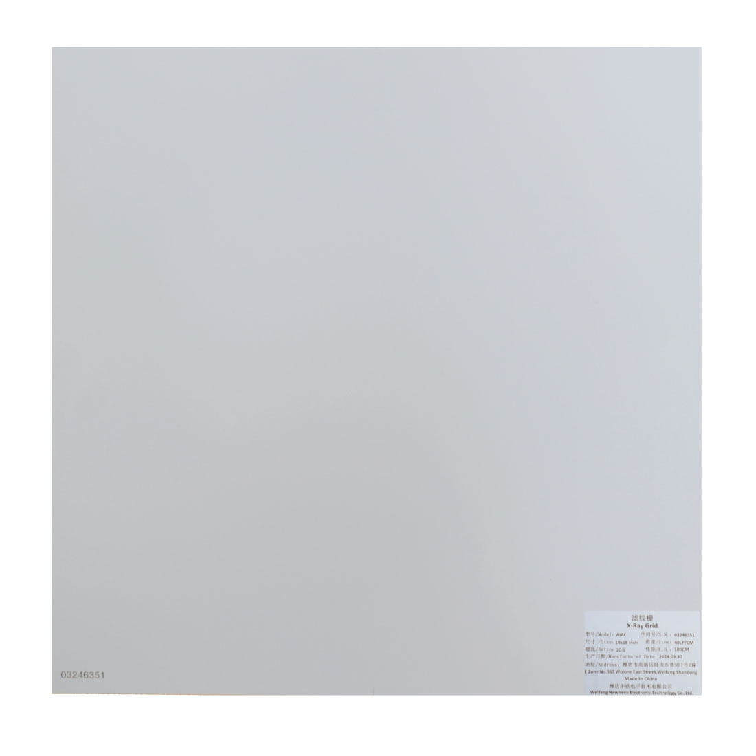
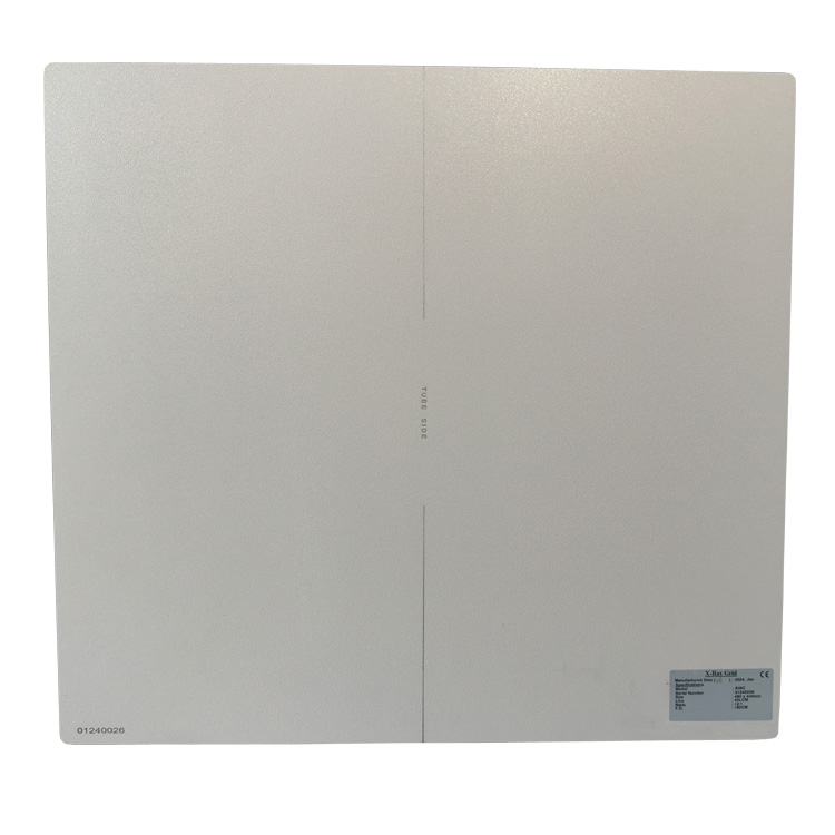
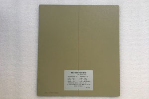
The grid is divided into the focal plane and the back focal plane. The focal plane is the side facing the focal point of the X-ray tube, also called the “incidence plane”. There are X-ray tube marks or notes on the focal plane, and the center line of the grid is marked. When using, the focal plane must face the direction of the X-ray tube. At the same time, technical parameters such as the focal length, grid ratio and grid density of the grid must be marked on the upper right corner of the panel to indicate its internal performance.
The following two aspects must be paid attention to when using the grid.
Effects of Defocus and Focal Length Mismatch
1. Tube voltage compensation
Since the main component material of the wire grid is lead foil, it not only blocks the scattered rays, but also inevitably blocks a part of the original emission line, which reduces the sensitivity of the film to a certain extent, so the wire grid is not used in photography. To properly increase the exposure conditions, that is, by increasing the tube voltage to improve the X-ray penetration, in order to achieve the purpose of compensation. Specific compensation data should be obtained in combination with clinical use
In general, low grid ratio grids are suitable for low kV tube voltages; high grid ratios are suitable for high kV tube voltages.
2. The effect of focus deviation and focal length mismatch
The lead bars of the converging grid are arranged in the focal direction. The converging line should be coincident with the focal point of the X-ray tube during photography, so that the original emission line is parallel to the lead bar and can pass through smoothly, while the direction of the scattering line is random. It is consistent with the direction of the lead strip, so most of it is absorbed by the lead strip, and the obtained image has better clarity. If the focal point of the X-ray tube and the convergence line of the filter grid deviate, or the filter grid is not placed at the specified focal length, the loss of the original emission line will inevitably occur. , and has a direct multiple relationship with the grid ratio of the grid. Therefore, the grid should be placed in the required position as much as possible. However, in actual clinical use, some deviations are unavoidable, so there is no regulation for the deviation of the grid.
a. Center deviation should be avoided as much as possible. In the case of a static grid, there should be no deviation; when a movable grid is used, there will inevitably be a center deviation, but the deviation should be designed to be as small as possible.
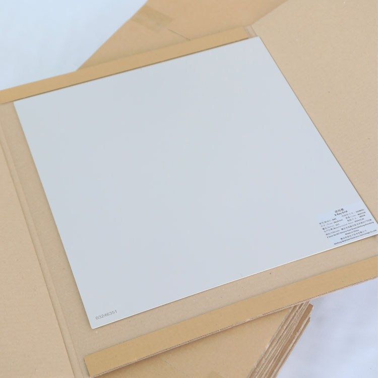
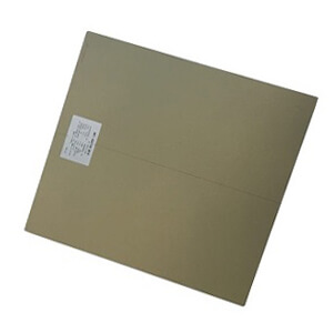
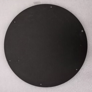
b. In some occasions, the distance from the focal point to the film cassette needs to be changed according to the different parts to be illuminated, but the filter grid cannot be replaced frequently, so only one allowable range of focal length change can be specified. When the transmittance of the original emission line at the edge of the effective area of the grid decreases by 40%, the film distance at this time is the limit value. As a general rule, the change in film distance should be no greater or less than 25% of the focal length of the grid. Therefore, the focal length indicated on the wire grid is the nominal focal length, and the actual usable focal length has a certain range. The filter DR wire grid picture is as follows:
Author:X Ray Grids Maker
Tel: +86 17616362240
Email: newheek1999@outlook.com
Company: Weifang Newheek Electronic Tech Co., Ltd.
Address: E Building of Future Star Scientific Innovation Industrial Zone of No.957 Wolong East Street, Yulong Community, Xincheng Sub-District Office, Weifang Hi-tech Zone, Shandong Province, China